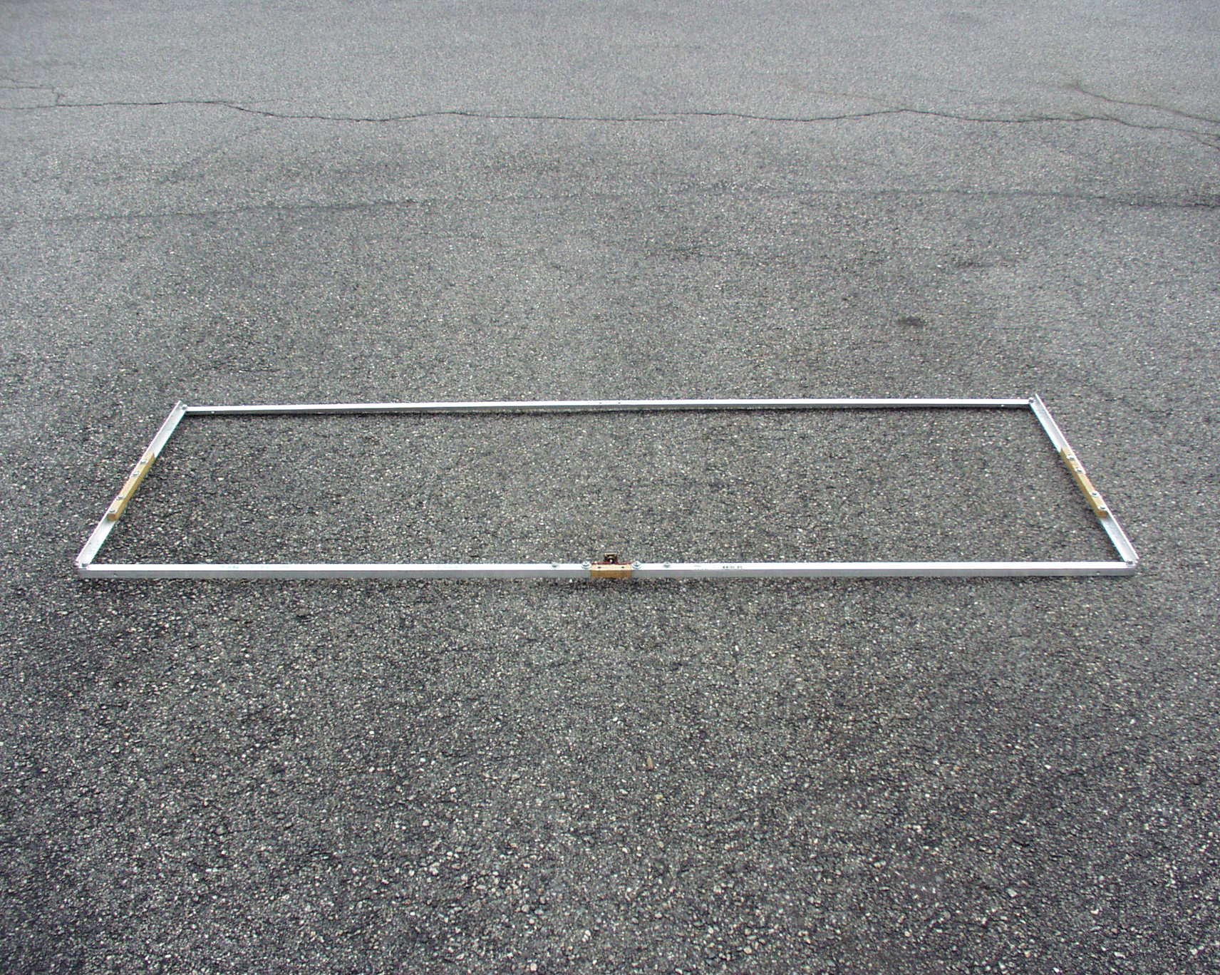
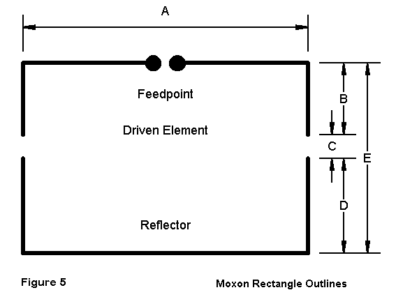
| This is a picture of the whole antenna on the ground in my
driveway. The driven element is in front and the reflector is in the rear. |
 |
 |
It is constructed of 3/4" by 3/4" aluminium angle stock. |
| The dimensions are approximately 29 inches deep by just under
7 feet long. Exact dimensions will be given later. |
 |
 |
In this antenna, the aluminium angle stock is cut into seven pieces:
- One long piece which forms part of the reflector.
- Two long side pieces which forms part of the reflector.
- Two short side pieces which form part of the driven element.
- Two long pieces which form part of the driven element.
|
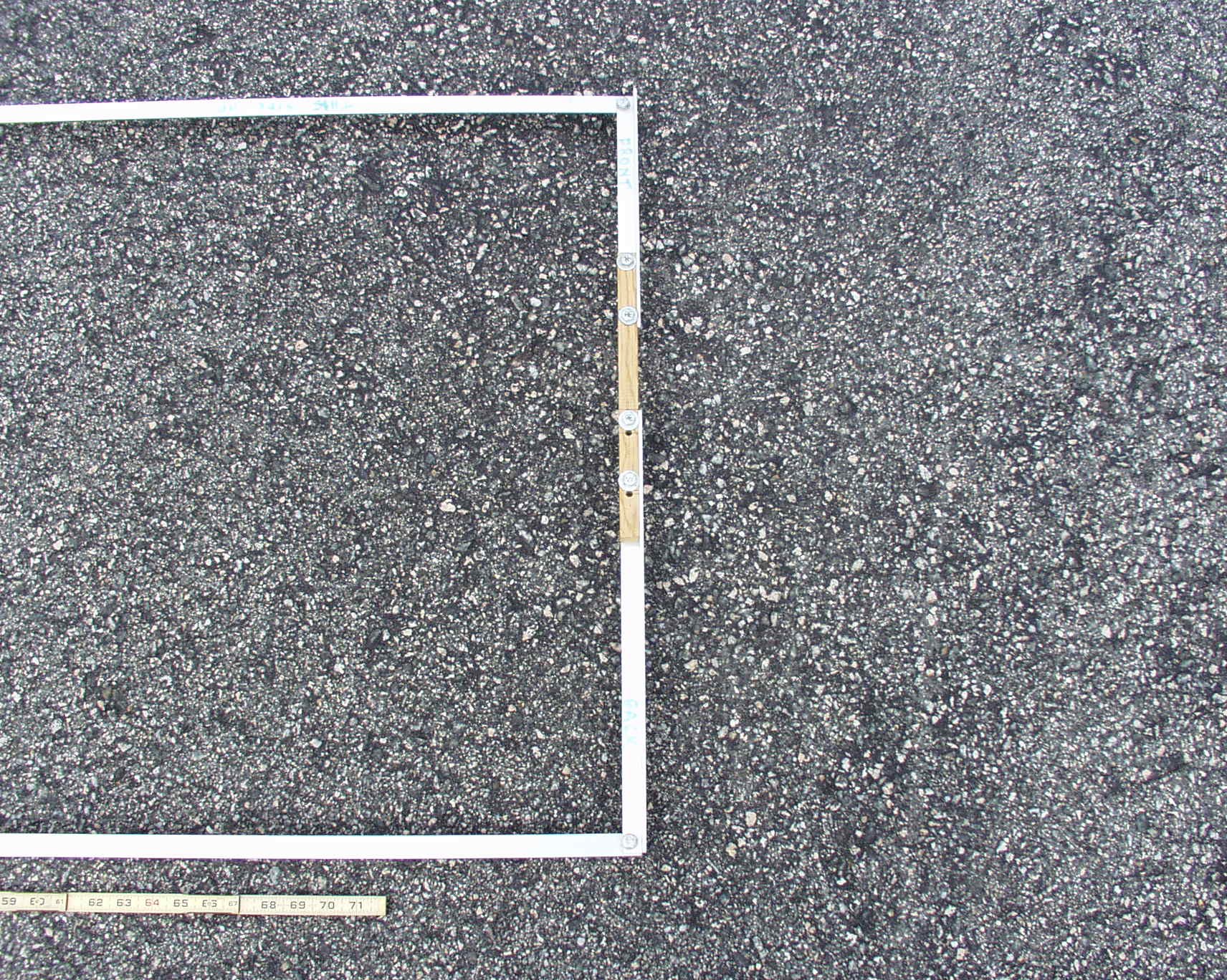
| The side pieces are joined together with a piece of 3/4" by
3/4" molding and 1/4 x 20 bolts and nuts. The wood lays inside of the angle
stock. |
 |
 |
In a similar fashion, the two pieces of the driven element are
joined together with a piece of 3/4" by 3/4" molding and 1/4 x 20 bolts and
nuts. Attached to the inner ends of the driven element pieces is an SO-239
supported by #12 wire. |
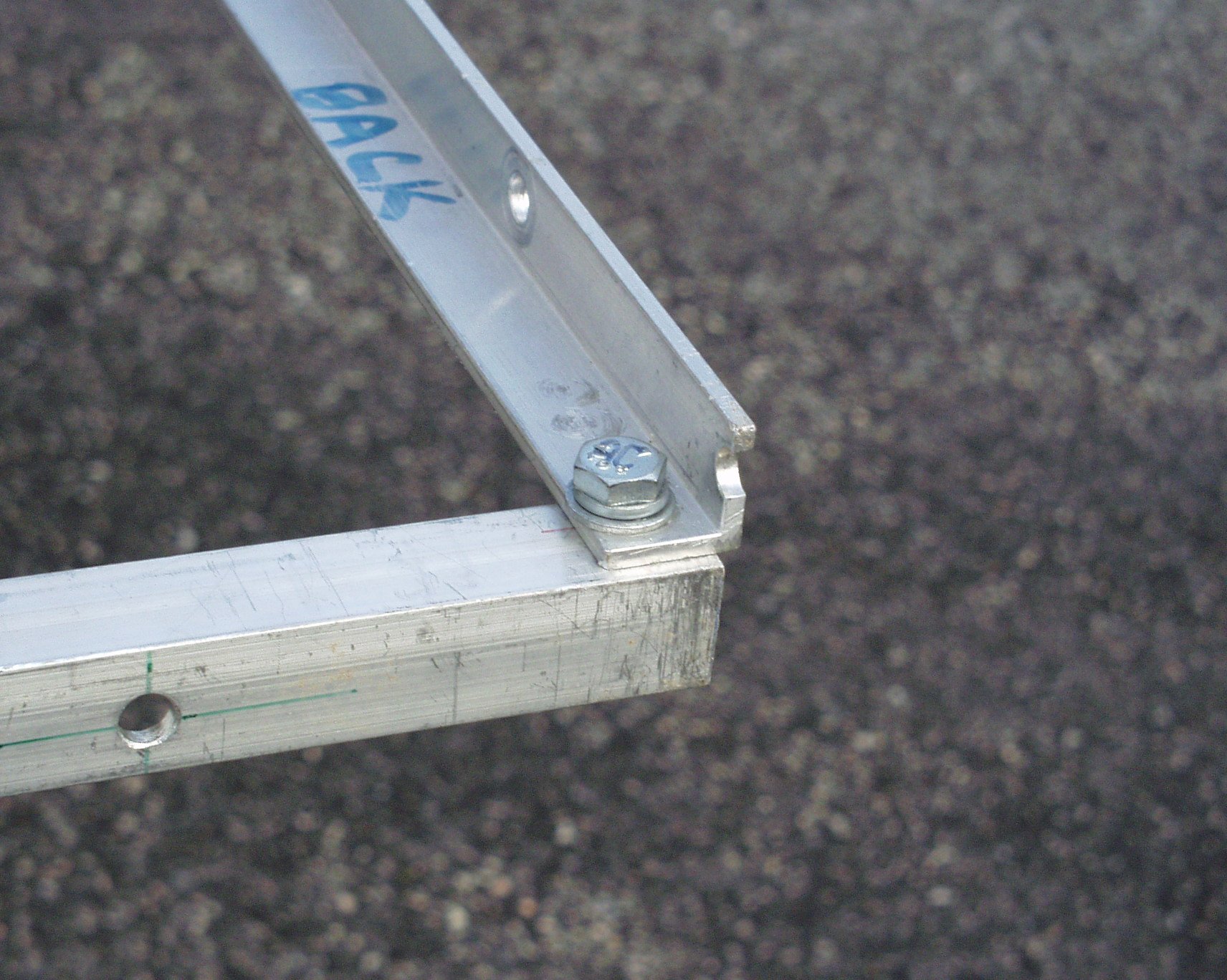
| With both sides and the driven element joined together like
this, there are now only four sides and four assemblies that have to be bolted
together at their corners. Again, I use 1/4 x 20 bolts and nuts. Holes for the
screws are drilled approximately 3/8" in from the ends and are centered on the
inside of the angle stock. The extra holes in the picture about 3" in from the
ends are used when storing the antenna for travel. |
 |
| Attaching the antenna to the mast is a boom made from a piece
of 1" schedule 40 PVC pipe. It is slightly longer than the depth of the antenna.
Radio shack U-bolts with brackets fasten the antenna to the boom. The first
picture is how the driven element is done and the second picture is the
reflector. On the director U-bolt, do not use fender washers. Just use flat
washers - they are not as wide and will not short out the driven element feed.
Also, make sure that the connections between the SO-239 and the driven element
do not short out to the U-bolt or its bracket. |
 |
 |
 |
Holding the whole thing to the mast is a homebrew boom to mast
adapter. It is made from a blank steel cover for a 5" electrical box and 4 Radio
Shack U-bolts with brackets. |
| Feeding this whole thing is a piece of RG-58 coiled into a
choke balun. There are 3 turns in a 5" diameter coil. The cable is a Radio
Shack 6' jumper with a male connector on one end and a female connector on
the other. |
 |

